

What Is the Best Electronic Power Transformer in 2026?
In 2026, the best Electronic Power Transformer depends on the equipment it must serve, not just its advertised efficiency. A compact unit feeding a control cabinet faces different demands from one supporting a motor drive or data-center power system. Voltage range, frequency, isolation, thermal limits, and installation space all matter. Small details count. A transformer that fits neatly on a drawing may run hot beside a dusty machine. That is where specifications meet real operating conditions.
A dependable comparison begins with verified ratings and clear application requirements. Check input and output voltage, rated power, load profile, cooling method, protection features, and expected operating environment. Then review manufacturer datasheets, test information, and warranty terms. Do not compare efficiency figures without checking how and under what conditions they were measured. A high-efficiency rating can look impressive, yet poor thermal performance or incompatible connections may make a unit unsuitable. For installations with sensitive electronics, confirm that isolation and output characteristics match the equipment’s needs. These details are easy to overlook.
There is no universal winner. The right choice may balance efficiency, reliability, service access, and total cost rather than maximize one headline specification. Even a careful shortlist can miss a constraint discovered only during installation. This guide explains how to compare transformer types, evaluate practical performance, and identify questions to ask suppliers before choosing a model. It aims to make the decision clearer, while recognizing that project-specific engineering review still matters.
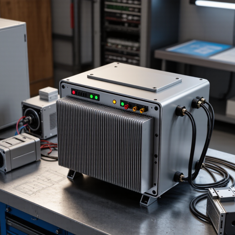
What an Electronic Power Transformer Is
An electronic power transformer, often called a solid-state transformer, uses semiconductor switches and control circuits alongside a transformer. Unlike a conventional unit, it can convert incoming AC to DC, pass energy through a high-frequency isolation stage, then provide controlled AC or DC output. The exact design varies. The name is not perfectly standardized.
Picture a cabinet receiving medium-voltage AC and supplying a regulated DC bus to a charger or storage system. Sensors and switching controls can respond to changing loads. That added control can be useful. It also adds components, heat, and failure points, so “electronic” does not automatically mean more efficient or more reliable.
The U.S. Department of Energy’s 2016 technical-support analysis estimated about 61 terawatt-hours of annual losses across the installed distribution-transformer fleet. That figure describes conventional fleet losses, not savings proven for electronic transformers. It shows why efficiency deserves attention, but comparisons need matching voltage, load, and operating conditions. A light-load test can mislead. For a 2026 purchase decision, check conversion losses, cooling needs, isolation, overload behavior, and maintenance requirements against the actual application.

How Electronic Power Transformers Convert and Control Power
An electronic power transformer does more than change voltage. It uses semiconductor switches and control circuits to shape how electrical energy moves between a source and a load. In many designs, incoming AC is converted to DC, adjusted on a DC link, then converted back to AC at the required voltage or frequency. A high-frequency transformer may provide electrical isolation within this process. The exact layout varies.
Picture a cabinet receiving fluctuating AC from a supply. Sensors track voltage, current, and temperature, while a controller adjusts switching in rapid pulses. This can help regulate output when loads change, such as a motor speeding up or slowing down. Some systems can also support bidirectional power flow, but only when designed for it. Control is not magic.
For a real installation, “best” depends on load range, isolation needs, cooling, fault response, and service access. A compact unit may save space, yet still need careful thermal management. Switching devices create heat and electrical noise; filters and enclosure design matter. The label can mislead. Compare measured efficiency across expected operating loads, not just a single peak figure. And check how the system behaves during overloads, startup, and maintenance. A specification sheet rarely tells the whole story.
| Technology | How It Converts and Controls Power | Typical Switching or Operating Frequency | Typical Power Class | Indicative Efficiency | Main Strength | Best-Fit Applications |
|---|---|---|---|---|---|---|
| Conventional line-frequency transformer | Transfers AC energy through magnetic coupling at the supply frequency; turns ratio sets the nominal voltage change. | 50 or 60 Hz | From small units to utility-scale equipment | Often about 97–99% for well-designed medium- and large-power units; varies with rating and load. | Robust, mature technology with straightforward galvanic isolation. | Distribution, industrial AC systems, and applications that do not require high-frequency conversion or fast electronic control. |
| Isolated flyback converter | A switch stores energy in the magnetic component and transfers it to the output during the switching cycle; feedback adjusts the output voltage. | Typically tens to a few hundred kilohertz | Commonly a few watts to around 150 W; higher ratings are possible with suitable designs. | Roughly 75–90% for many designs, depending on power, topology, and operating conditions. | Relatively simple and economical for low-power isolated outputs. | Auxiliary supplies, adapters, and low-power control electronics. |
| LLC resonant converter with a high-frequency transformer | Resonant switching drives a high-frequency transformer; frequency or control timing is adjusted to regulate the output while reducing switching losses. | Typically tens to several hundred kilohertz | Often hundreds of watts to several kilowatts | Commonly about 90–97% for the converter stage, depending on design and load. | High efficiency and power density when designed for its intended operating range. | Server and telecom power supplies, industrial supplies, and other regulated isolated DC outputs. |
| Dual-active-bridge (DAB) converter | Two active bridges exchange power through a high-frequency transformer; phase shift between bridge waveforms controls power flow, which can be bidirectional. | Typically tens to a few hundred kilohertz | Commonly kilowatts to hundreds of kilowatts, subject to system design. | Often about 95–98% near its designed operating conditions; efficiency varies with voltage ratio and load. | Controlled bidirectional power transfer with galvanic isolation. | Battery energy storage, electric-vehicle charging systems, and DC microgrids. |
| Solid-state transformer (SST) system | Uses power-electronic conversion stages and usually a high-frequency isolation stage to transform voltage and actively manage power flow, voltage, or reactive power. | Switching frequency is topology-dependent, commonly in the kilohertz range or higher. | Modular systems range from tens of kilowatts to megawatt-class installations. | Typically about 95–98% for the complete conversion system in reported designs; results depend strongly on topology and operating point. | Combines voltage conversion with fast electronic control and potential AC/DC interfacing. | Applications needing controllable, multifunction power conversion, such as advanced distribution, traction, and charging infrastructure. |
| Selection note: There is no single best electronic power transformer for every application. Compare the required input and output voltage, power rating, isolation, bidirectional operation, efficiency across the expected load range, cooling, protection, and applicable safety standards. Frequency, power, and efficiency figures are indicative design ranges, not guaranteed specifications. Converter efficiency figures describe the overall conversion stage or system, not the high-frequency transformer component alone. | ||||||
Main Transformer Types and Their Applications
Choosing the best electronic power transformer in 2026 depends on the load, voltage, space, and operating conditions. Oil-immersed power transformers handle high voltages and large loads at substations. Distribution transformers then step voltage down for buildings, workshops, and homes. A quiet unit beside a neighborhood pole is a familiar example. Fit matters more.
Dry-type transformers use air or resin insulation, making them useful indoors where limiting oil-related fire risks matters. Instrument transformers, including current and voltage types, provide scaled signals for metering and protection. Isolation transformers separate circuits and can reduce electrical noise in sensitive equipment. High-frequency electronic transformers serve compact power supplies and converters, where switching electronics can reduce size. They are not interchangeable with conventional grid transformers.
The International Energy Agency’s 2023 report, Electricity Grids and Secure Energy Transitions, says annual grid investment needs to rise from about USD 300 billion to more than USD 600 billion by 2030. That expansion increases the need for suitable transformer capacity, but it does not identify one best type. Engineers still need to check load profiles, cooling, harmonics, and maintenance access. A neat specification can miss a messy real-world detail: future load growth.
Key Performance Factors for Comparing Models in 2026
In 2026, the best electronic power transformer is the one that fits its real operating conditions, not simply the model with the highest headline rating. Start with input and output voltage, rated power, and expected load range. Check output regulation during load changes, not only at a steady bench condition. Small differences matter. A unit running near its limit may heat up faster and leave less room for future equipment.
Efficiency should be compared at several load levels, since a system may spend most of its time below full power. Review thermal limits and cooling requirements, too. A compact enclosure with restricted airflow can behave differently from an open test setup. Watch for switching noise, electrical interference, and inrush current where sensitive equipment is connected. Noise matters. Request test conditions and measured data; a single efficiency figure rarely tells the whole story.
Safety isolation, overload response, short-circuit protection, and temperature monitoring deserve equal attention. Confirm that ratings match the installation, including ambient temperature and ventilation. If possible, evaluate a sample under the actual load profile and measure temperature, output stability, and noise after sustained operation. Datasheets can be incomplete, and that is worth questioning. The most reliable comparison combines documented specifications with practical testing and a clear margin for peak demand.
How to Choose a Transformer for Safety and Compatibility
Choosing the best electronic power transformer in 2026 starts with the equipment, not the price. Check the supply voltage, required output voltage, frequency, and whether the load needs AC or DC. A transformer alone does not convert AC to DC. Match its continuous power rating to the load, and allow extra capacity for motors or devices with high startup demand. Small mismatch, big trouble.
Safety details deserve equal attention. Look for specified isolation, insulation class, temperature limits, and overcurrent protection. The enclosure should suit its location; a dusty workshop and a clean indoor cabinet are not the same environment. Check the product documentation for recognized safety approvals in your region, and have a qualified professional review uncertain installations. Keep ventilation paths clear. Heat needs somewhere to go.
Compatibility also depends on physical fit, wiring terminals, and the load’s behavior over time. Compare the transformer’s output rating with the device label, then check whether the rating is continuous or conditional on cooling. I would not rely on a quick voltage reading alone; an unloaded transformer can behave differently under load. That check is easy to overlook. For a practical assessment, measure output under normal operating conditions and watch for unusual warmth, noise, or voltage drop. If the specifications are vague, pause before connecting valuable equipment.
How to use this comparison: Choose a transformer whose input-voltage range covers the supply where it will be used, and whose output matches the equipment’s requirements. The chart shows representative nominal mains voltages; local supply can vary. Check the device label and local electrical requirements, including frequency, grounding, and applicable safety certifications, before selecting a transformer.